【Graphitization】Principles and Process Explained (Latest)

Graphite electrodes are primarily used in electric arc furnace (EAF) steelmaking, serving as a crucial high-temperature conductive material. They are also widely applied in the aluminum industry, electrolytic cells, and chemical equipment as conductive and heat-resistant components.
【Graphitization】Principles and Process Explained (Latest)
Let's analyze in detail the principles and processes of graphitization. This is a very important industrial process in fields such as lithium-ion batteries, metallurgy, and electrical engineering.
I. Principles of Graphitization
Core Definition: Graphitization refers to the physicochemical process in which carbon atoms transform from a disordered "turbostratic carbon" structure to a well-ordered "graphite" crystal structure under high-temperature heat treatment (usually above 2200°C).
1. Structural Transformation: From "Turbostratic Structure" to "Graphite Crystal Structure"
① Precursor (Raw Material) Structure: Carbon materials such as petroleum coke, needle coke, and pitch coke, after carbonization treatment at approximately 1200°C, mainly exhibit a turbostratic structure.
② Turbostratic Structure Characteristics: Carbon atoms primarily form hexagonal planar molecules (similar to single-layer graphene), but these planar molecules are limited in size, arranged disorderly between layers, with a relatively large interlayer spacing (about 0.344 nm), and contain numerous defects and heteroatoms (such as H, O, N, S, etc.).
③ Analogy: It can be imagined as a stack of papers that are disordered, skewed, and of uneven size.
④ Graphitization Process: At ultra-high temperatures, carbon atoms gain sufficient energy and undergo drastic structural adjustments:
⑤ Heteroatom Release: Chemical bonds break, and non-carbon atoms escape as gases (such as CH₄, CO, H₂, etc.), purifying the carbon lattice.
⑥ Growth of Carbon Planes: Small carbon planes merge and enlarge, forming larger and more complete planar layers.
⑦ Interlayer Rearrangement: The originally disordered layered structures start to move relative to each other and align, tending toward ABAB… or ABCABC… regular stacking (i.e., the three-dimensional crystal structure of graphite).
⑧ Interlayer Distance Reduction: The distance between layers decreases to the ideal graphite crystal level (0.3354 nm).
⑨ Final Product Structure: Highly ordered graphite crystal structure.
⑩ Graphite Structural Characteristics: Carbon atoms form large planar molecules via sp² hybridization, with strong covalent bonds within layers and weak van der Waals forces between layers. It exhibits anisotropy and excellent electrical and thermal conductivity.
⑪ Analogy: It can be imagined as a stack of papers placed extremely neatly, with edges aligned.
2. Driving Force and Conditions of Graphitization
① Temperature: The most critical factor. The higher the temperature, the greater the kinetic energy of the atoms, which facilitates structural rearrangement and defect repair. Industrially, it is usually carried out at 2800–3200°C.
② Time: Sufficient time at a specific temperature is required to allow atomic diffusion and structural adjustment to fully occur.
③ Catalysts: Certain elements (such as Fe, Co, Ni, B, etc.) can act as catalysts, lowering the activation energy required for graphitization, allowing a higher degree of graphitization at relatively lower temperatures. This is called catalytic graphitization.
④ Pressure: Appropriate mechanical pressure helps the orientation and ordering of graphite microcrystals.
3. How to Measure the Degree of Graphitization?
The degree of graphitization (g) is commonly used to represent it, ranging from 0% (completely disordered) to 100% (perfect crystal). It is mainly measured by X-ray diffraction (XRD). The calculation formula is based on the interlayer spacing of the (002) plane (d₀₀₂):
g = (0.3440 - d₀₀₂) / (0.3440 - 0.3354) * 100%
Where 0.3440 nm is the interlayer spacing of the turbostratic structure, and 0.3354 nm is the interlayer spacing of ideal graphite.
II. Graphitization Process
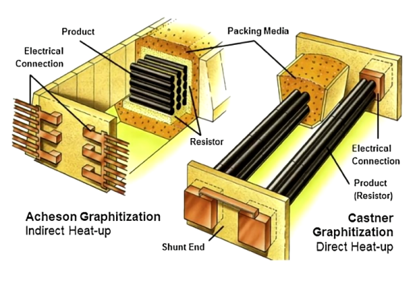
Achieving ultra-high-temperature conditions industrially is the core challenge. The main processes are based on large-scale resistance furnaces, utilizing the resistance of the material itself or a graphite heating element to generate Joule heat when electrified to reach high temperatures.

1. Acheson Furnace
The most traditional and widely used process.
Process:
① Charging: Mix the carbon material to be graphitized (such as petroleum coke) with resistive material (usually metallurgical coke granules) and fill it into the furnace chamber. The furnace has fixed conductive electrodes on both sides.
② Insulation: Cover the furnace charge with thick insulating materials (such as carbon black, sand, perlite) to reduce heat loss and protect the product from oxidation.
③ Electrical Heating: A strong current (tens of thousands of amperes) is passed through. The current mainly heats the resistive material, and the heat is conducted to the material being processed, achieving graphitization. The heating process is slow, usually lasting tens of hours.
④ Cooling: After heating, cut off the power and allow the furnace to cool naturally (may take a week or longer).
⑤ Unloading: Remove the insulation material and take out the graphitized product.
Advantages:
Mature technology, capable of processing large amounts of material, wide applicability.
Disadvantages:
Extremely high energy consumption (electricity is the major cost), long production cycle (weeks), poor temperature uniformity control, dust pollution.
2. Longitudinal Graphitization Furnace (LWG)
A more modern and efficient process, especially suitable for producing long, rod-shaped products like graphite electrodes.
Process:
① Carbon blanks are connected end-to-end and arranged in a straight column inside the furnace, with both ends connected to massive conductive copper clamps. The entire furnace body is surrounded by insulation.
② When electrified, the current flows directly through the material being processed, generating heat via its own resistance.
Advantages:
① Energy-saving: No resistive material needed; heat is generated internally, higher thermal efficiency, saving 20–30% electricity compared with Acheson furnace.
② Uniform Heating: Products are heated evenly, resulting in more consistent quality.
③ Shorter Production Cycle: Faster heating and cooling.
Disadvantages:
High requirements for uniformity in size and physicochemical properties of blanks, more complex equipment.
3. Continuous Graphitization Furnace
The future development direction, aiming for automated, continuous production, mainly used for powdered materials like anode materials.
Process: Material is continuously heated and graphitized in a high-temperature tubular furnace (such as carbon tube furnace or induction furnace) or vertical furnace under inert gas protection.
Advantages:
① Extreme Energy Efficiency: High heat utilization.
② Ultra-high Efficiency: No intermittent downtime, high production capacity.
③ High Automation: Stable product quality.
④ Environmentally Friendly: Fully enclosed, no dust leakage.
Disadvantages:
High technical difficulty, high equipment investment, currently mainly for powder materials; still challenging for large-size products.
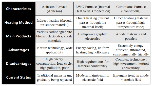
4. Summary and Comparison

We hope the above detailed explanation helps you comprehensively understand the principles and processes of graphitization.
Feel free to contact us anytime for more information about the Graphite Products market. Our team is dedicated to providing you with in-depth insights and customized assistance based on your needs. Whether you have questions about product specifications, market trends, or pricing, we are here to help.
No related results found


0 Replies