


Acheson furnace
Acheson furnace
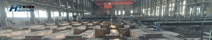
Acheson graphitization furnace is a type of graphitization furnace named after inventor Acheson. Acheson furnace was invented in 1895 and first patented in the United States. Its prototype is: in the long furnace constructed of refractory, UHP graphite electrode with best performance in steelmaking. carbon blank and granular material are filled to form a conductive furnace core, and heat insulation materials are around the furnace core. Conductive electrodes are arranged on the wall of the two upper ends of the furnace head, and are connected with the power supply to form an energized loop. When the circuit is connected, the furnace core due to the role of resistance that heating up, so that the carbon billet in 2200~2300℃ temperature, after high temperature heat treatment and transformed into artificial graphite.

As Acheson graphitization furnace is the main furnace type of graphitization production in carbon industry, it is very important to find out the electric heating efficiency and energy balance of Acheson graphitization furnace for graphitization production of carbon products and energy saving of graphitization furnace. According to the law of energy conservation, for the Acheson graphitization furnace which converts electric energy into heat energy to heat graphite products, the temperature in the graphitization furnace core at each time can be calculated theoretically from the numerical value of electric energy, but the temperature in the furnace core can not be completely calculated only by Joule Lenz law Q=0.24IRT. Because in addition to heating furnace core products and raising furnace core temperature, a large part of resistance heat is lost through various ways. Then, how much of the total electric energy is used to heat the furnace core, how much energy is used to raise the temperature of the furnace core, and how much energy is lost through various ways. According to the law of energy conservation, these three are in balance.
That is: Q total =Q1+ Q2
Q total -- Energy supplied to the furnace during power on time;
Q1 -- Energy absorbed in furnace;
Q2 -- Energy lost from the furnace
From the analysis of electric heating balance of Acheson graphitization furnace, it can be seen that graphitization furnace is a thermal equipment with large power consumption. Therefore, how to reduce the electricity consumption under the premise of ensuring product quality is the main content of the energy saving of the graphitization furnace, and also the only way to reduce the production cost of graphitization. The energy saving of Acheson graphitization furnace and the graphitization difficulty of its products are also one of the factors affecting the power consumption of graphitization process. In addition to improving the graphitization yield of products and reducing various types of waste products, we can also improve the graphitization process technology, enhance the thermal insulation effect of thermal insulation materials, improve the structure of graphitization furnace and prevent the oxidation of conductive electrodes, change the connection mode between graphitization furnace and power transformation and distribution transformer system to reduce the power consumption of graphitization process of Acheson graphitization furnace and save energy.
1) The impregnated electrode with large cross section shall be selected for the material and specification of conductive electrode;
2) When the transformer is matched with the graphitization furnace, the number of conductive electrode groups distributed on the end face of the graphitization furnace shall be reasonably selected, and the current density shall be controlled below 6.25 A/cm2;
3) The water supply cooling time of Acheson graphitization furnace should be controlled within 14~16h after power transmission according to product specifications and transmission curve speed;
4) At the end of each operation cycle of graphitization furnace, check the resistance of conductive electrode in time to ensure the operation capacity of graphitization furnace and prevent production accidents.
DC graphitization furnace refers to a resistance furnace which uses carbon baked products and resistance materials as the furnace core and is connected with DC to produce artificial graphite products. Due to the resistance of the furnace core (mainly resistance of resistance material), the electric energy can be converted into heat energy when the current flows, and the carbon baked products can be heated to a high temperature of 2000 ~ 3000 ℃ to complete the graphitization process and become artificial graphite. It belongs to Acheson furnace together with AC graphitization furnace.
Brief history in the 1960s, DC graphitization technology began to develop in developed countries in Europe and America. Compared with AC graphitization furnace, it has significant advantages of large capacity, good product quality and low energy consumption, so it has attracted universal interest and attention all over the world. The start of DC graphitization furnace in China is a little late.
In October 1972, the furnace equipped with 3000kV·A rectifying transformer combined with 9M furnace was first applied in the production of Beijing Carbon Plant. Compared with AC graphitization furnace, it not only takes less time to transmit electricity, but also saves electricity by more than 25%.
In January 1973, after 13,500kV·A rectifying transformer with 18m furnace was put into production in Nantong Carbon Plant, the power on time was shortened by 20h and the power consumption was reduced to less than 4000kW·h/t.
In September 1975, 16000kV·A DC furnace of Jilin Carbon Plant and 3340kV·A DC furnace of Shijiazhuang graphite electrode plant were put into operation at the same time.
By 1986, China had 136,000 kV·A AC graphitization furnace, accounting for only 27% of the total installed capacity of graphitization furnace in that year. The DC graphitization furnace has an installed capacity of 175,000 kV·A, accounting for 73%. The graphitization technology in China has reached a new level.
For the strengthening of graphitization process, in addition to adopting high-capacity rectifying transformer unit on the equipment, appropriately increasing the length and core area of the furnace and matching with the transformer, the following measures shall be taken in process operation:
(1) Resistance materials with low resistivity and insulation materials with low thermal conductivity and low conductivity are used.
(2) Improve the quality of baked blanks.
(3) Adopt the size specification collocation furnace loading method and dislocation 1/2D furnace loading method.
(4) Realize the mechanization of loading and discharging, shorten the cooling time of the way and improve the turnover rate
Furnace structure and characteristics
DC graphitization furnace and AC graphitization furnace have the same structure except for different power supply equipment. The power supply equipment of DC graphitization furnace is composed of three-phase AC main regulator, a transformer and corresponding rectifier equipment. DC power supply to the furnace has the following advantages:
(1) Since the adopted power supply transformer is three-phase, it will not have the impact of three-phase load imbalance on the power grid. It can increase the capacity of the transformer, strengthen the graphitization process and increase the capacity of the graphitization furnace.
(2) The power factor of the whole power supply line is high, reaching above 0.9, and the effective utilization rate of electric energy is improved.
(3) DC has no alternating magnetic field and inductance loss, no surface effect and adjacent effect and other electrical loss, high electrical efficiency.
The improvement of power supply conditions of DC graphitization furnace creates conditions for strengthening graphitization process. Since the power grid has no limit on the capacity of transformers, high-power transformers and rectifier units can be used, with small DC loss and high utilization rate, so the furnace core can get more electric energy. If the furnace core with appropriate size is matched, the power per unit volume can reach more than 160kW/m3 (60% larger than AC furnace) and the current density can reach 2.0A/cm2 above (100% larger than AC furnace), with such conditions, rapid power transmission can be realized, and the graphitization temperature can reach 2700 ℃ (about 400 ℃ higher than that of AC furnace) in a short time. Due to the shortening of power transmission time, the furnace capacity can be improved and the power consumption of graphitization can be reduced to less than 4000kW·h/t (about 20% lower than that of AC furnace). With the increase of graphitization temperature, graphitization can be carried out more completely, so the product quality is improved. In short, the DC graphitization furnace can realize the operation of high power, high electric density and fast curve, so as to achieve the goal of high yield, high quality and power saving, which is the strengthening of the graphitization process.
In the trial production of anode plate in large DC graphitization furnace, the charging process is the same as that of AC graphitization. The product is vertically hung and horizontally installed in the furnace in the direction of the furnace length. About 200 anodes are hoisted each time. The anodes are close to each other. The interval between the hoists is about 50mm, and the raw metallurgical coke with particle size of 25mm is filled as resistance material. When normal power transmission curve is adopted and the final furnace is powered off, the secondary voltage is 120-130 V and the secondary current is 125,000 A.
This strange waste phenomenon can be explained as: in the process of DC graphitization, the furnace top and end of the graphitization furnace are respectively connected with the positive pole and the negative pole. At this time, if there is no gap between two adjacent anodes in the crane or there is no resistance material filling, there will be a potential difference between the two anodes.
This waste can be reduced by limiting the current. In the trial production, we have used this method to limit the secondary current to no more than 80,000 amperes. Although it is effective, the production of limited current is actually the production of pressure load, thus limiting the production capacity of large DC graphitization furnace.
It is a better way to improve the charging process to prevent the gap between the two anodes, avoid potential difference and destroy the two conditions at the same time. In the trial production, a charging process completely different from AC graphitization was adopted. We divided the anode plate into several units and loaded them into the furnace. The surrounding of each unit was filled with resistance materials, so that the furnace was like loading several large electrodes, so as to eliminate the gap and electrical potential difference and prevent the generation of strange waste products.
We will focus on equipment, facility requirements and design, as well as production process requirements for bulk industrial production of graphitized products. I hope to get more technical guidance from the industry, and also hope to learn from experts to improve my scientific research ability, contact us to get more furnace technical guidance.
No related results found


0 Replies